Industrial Steam Steam Flow II
Steam Flow II Pressurized Deaerator
Features
- CONSTANT RECYCLING
 guarantees deaeration of all dissolved oxygen in excess of .005 cc/liter from 0% to 100% of deaerator capacity.
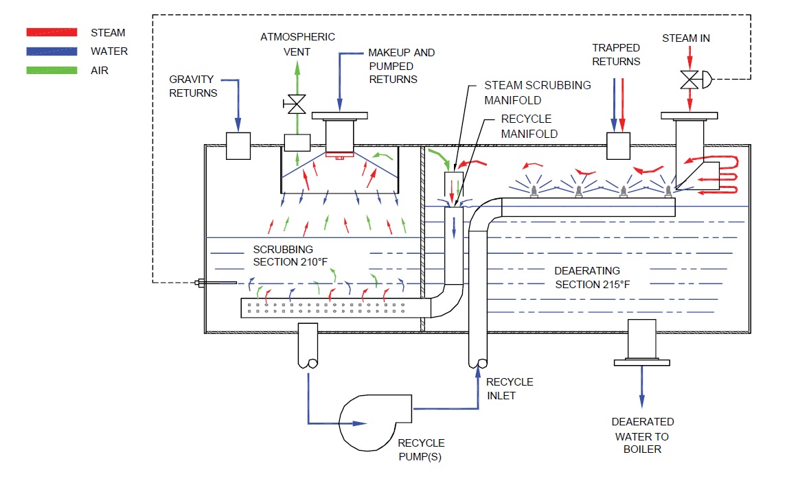
 - UNIQUE FULL PARTITION DEAERATOR DESIGN accepts gravity returns to the atmospheric scrubbing section along with make-up and pumped returns. Deaerating section accepts trapped returns for preferential use of flash steam.
- ELECTRONIC INSTRUMENTATION FOR MODULATING DEAERATOR LEVEL control includes a HART compatible differential pressure transmitter, PID controller, and motorized control valve.
- SEPARATE DEAERATING & MIXING SECTIONS offer a two stage continuous cycle which provides .005 cc/l deaerated water during all load conditions regardless of surges from the system.
- ONLY STAINLESS STEEL DEAERATOR components come in contact with undeaerated water.
- ATMOSPHERIC NON-CODE DEAERATOR VESSEL requires no annual shutdown for inspection.
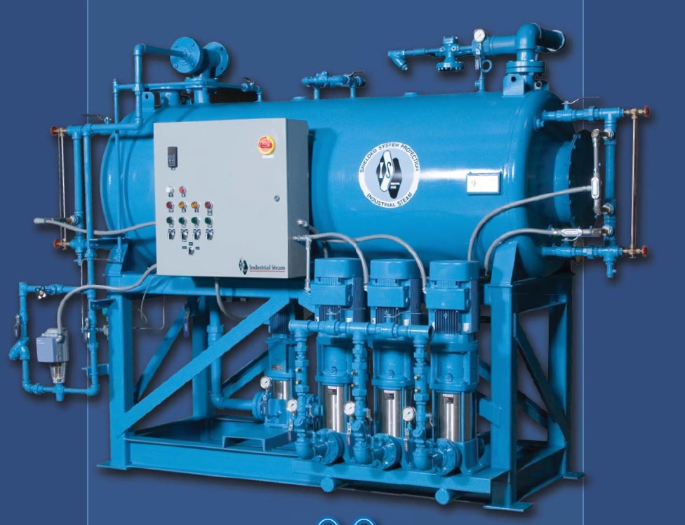
- CUSTOM ENGINEERED PACKAGED DEAERATOR SYSTEM includes boiler feedwater pumps and quality components to insure reliable
- Capacity LBS/HR: 3,450-125,000.
Advantages
- Industrial Steam’s exclusive constant recycling feature and the use of a partitioned receiver provide the advantages of a two-tank deaerator system as a single package. These advantages are available without the necessity for onsite erection or field installed piping. Expanded deaerating sections are standard for surge condensate loads.
- GUARANTEED DEAERATOR PERFORMANCE FROM0% to 100% of capacity regardless of load conditions is unmatched by any other deaerator.
- CUSTOM ENGINEERED PACKAGED DEAERATOR SYSTEMresults in a small foot print, minimal onsite installation costs, and a single source of responsibility for all major components.
Operation
Modulated make-up water is sprayed into the deaerator through a stainless steel spring loaded nozzle and into a stainless steel internal vent condenser located in the scrubbing section. The deaerator nozzle produces a thin conical sheet of water which condenses the vapors while permitting oxygen to exit through the unrestricted atmospheric vent. Pumped low temperature returns are also sprayed through the deaerator nozzle. Gravity returns flow unrestricted to the deaerator scrubbing section.
The combined make-up and returns in the deaerator scrubbing section are heated with steam and recycled deaerated water from the deaerating section.
Both the steam and deaerated water enter the deaerator scrubbing section through separate stainless steel manifolds. The perforated steam manifold provides jets of steam to vigorously scrub the major portion of the dissolved oxygen from the make-up, pumped returns, and gravity returns. The temperature in the scrubbing section is controlled at 210ºF (at sea level), which assures the release of the majority of the dissolved oxygen without flash loss.
The scrubbing section water, which is nearly fully deaerated, is continuously recycled to the deaerating section where it is sprayed through stainless steel, wide-angle, full-cone nozzles. Steam enters the deaerating section in response to the temperature in the scrubbing section. Since the cycle is continuous, pure steam is always available for final deaeration. The last traces of oxygen are removed at the point of contact with the purest steam. Excess, fully deaerated water flows continuously from the deaerating section to the scrubbing section through the stainless steel recycle manifold. Trapped returns are piped to the deaerating section where the flash steam is preferentially used for final deaeration.
Since the recycle pump capacity exceeds the deaerator capacity by at least 25%, the deaerator is able to meet .005 cc/l. From zero to 100% load. This same feature also enables the deaerator to supply fully deaerated water to the boiler on start-up. Rapid load changes and on-off boiler feedwater controls, which are very troublesome for other atmosphereic deaerators, will not affect the Spray Flow II Atmospheric Deaerator’s performance or operation.